【AD5933 阻抗轉換器】網路分析儀模組 1M採樣率12bit解析度 測量電阻


AD5933阻抗測量儀
一、產品描述
AD5933是一款高精度的阻抗轉換器系統解決方案,片上整合頻率產生器與12位元、 1 MSPS的類比數位轉換器(ADC) 。以頻率產生器產生的訊號來激勵外部複阻抗,外部阻抗的響應訊號由片上ADC進行取樣,然後由片上DSP進行離散傅立葉變換(DFT)處理。 DFT演算法在每個頻率上傳回一個實部(R)資料字和一個虛部(I)資料字。再根據實部資料字與虛部資料字可計算出待測元件的阻抗值與相位值。
二、產品特性
可程式輸出峰峰值激勵電壓,輸出頻率最高可達100 kHz
可程式頻率掃描功能和序列I2C®介面
頻率解析度: 27位元(<0.1 Hz)
阻抗測量範圍: 1 k Ω至10 M Ω
利用附加電路可測量100 Ω至1 k Ω阻抗
內部溫度感測器( ± 2 ° C)
內部系統時鐘選項
三、產品應用
- -電化學分析
- -生物電阻抗分析
- -阻抗頻譜分析
- -複阻抗測量
- -腐蝕監控和保護設備
- -生物醫學和汽車感測器
- -生物電阻抗分析
- -近程感測
- -無損檢測
- -材料性質分析
- -燃料/電池狀態監控
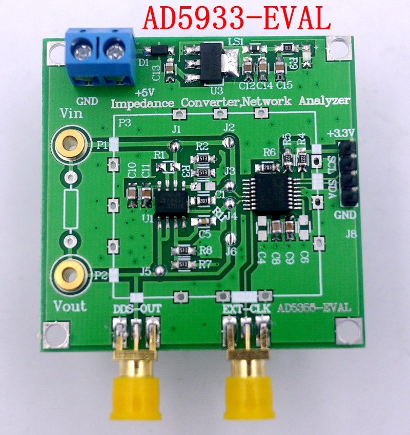
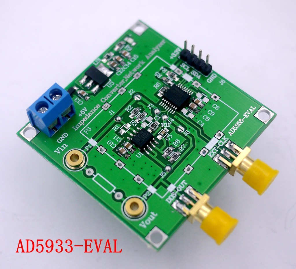
四、產品實體圖


五、原理圖(購買後提供以及參考資料)
六、模式配置
直通模式:連接J2 、 J6 ,斷開J1 、 J3 、 J4 、 J5 ,未知阻抗直接連在VIN與VOUT兩端
雙重運算模式:連接J1 、 J3 、 J4 、 J5 ,斷開J2 、 J6 ,增加8606雙運轉優化訊號鏈路
七、程序
#include "sys.h"
#include "ad5933.h"
#include "delay.h"
#include <math.h>
#define AD5933_ADDRESS 0x1A //定義AD5933從機位址,其預設序列匯流排位址為
//0001101(0x0D) ,但由於從機位址高七位為裝置地
//址(0x0D) ,故實際從機位址為裝置位址左移一位
//即(0x1A)
#define POINTER_COMMAND 0xB0 //定義指標設定指令(10110000)
#define Gain_factor 5.0725e-9
#define PI 3.1415926536
#define System_Phase 109.052767
#define rad_to_degree 180 / PI
double GainFactor[] = {5.1143e-9, 5.1146e-9, 5.1162e-9, 5.11645e-9, 5.11699e-9, 5.1175e-9, 5.11774e-9, 5. , 5.12105e-9};
double SystemPhase[] = {290.994, 291.721, 292.452, 293.168, 293.870, 294.596, 295.336, 296.009, 294.596, 295.336, 296.009, 296.750, 29629.29};
int Receive_byte[1]; //定義接收數組
short int status_register; //定義狀態暫存器變數
int Re, Im; //實部,虛部
double Magnitude, Impedance, Phase; //DFT幅度值,阻抗值,相位值
void AD5933_Init(void)
{
delay_ms(100); //這裡的延遲很重要
// Transmit to start frequency register
// program 30khz start frequency assuming internal osc of 16.776Khz
i2c_write ( 0x84, 0x45);
i2c_write ( 0x83, 0xA6);
i2c_write ( 0x82, 0x0E);
// Transmit to frequency increment register
// program 1Khz frequency increment assuming internal osc of 16.776Khz
i2c_write ( 0x87, 0x02);
i2c_write ( 0x86, 0x7D);
i2c_write ( 0x85, 0x00);
// Transmit to NUMBER OF INCREMENTS register
// program 10 frequency increments
i2c_write ( 0x89, 0x0A);
i2c_write ( 0x88, 0x00);
// Transmit to settling time cycles register
// program 15 output cycles at each frequency before a adc conversion
i2c_write ( 0x8B, 0x0F);
i2c_write ( 0x8A, 0x00);
// Transmit to CONTROL register
// place the AD5933 in standby mode
i2c_write ( 0x80, 0xB0);
// Choose the internal system clock
i2c_write ( 0x81, 0x00);
// initialise the sensor with contents of start frequency regsister with range 1 (2vp-p, 1.6v) PGA = x1
i2c_write ( 0x80, 0x11);
delay_ms(5); //這裡的延時是為了讓電路在發出初始化指令後達到穩定狀態
// start of frequency sweep (2vp-p, 1.6v) PGA = x1
i2c_write ( 0x80, 0x21);
// initialise the sweep sequence
}
void sweep (void)
{
unsigned int real_byte_high;
unsigned int real_byte_low;
unsigned int imag_byte_high;
unsigned int imag_byte_low;
signed short int imag_data;
signed short int real_data;
int m = 0; //增益因子數組與系統相位數組計數器
printf ("Start of Frequency sweep "); // printf function call
delay_ms(10);
for(;;)
// status reg D0 = valid temp, D1 = valid real/imag data, D2 = frequency sweep complete
{
// D1 status reg loop
status_register = AD5933_read(0x8F); // read the status register
status_register = (status_register & 0x2); // mask off the valid data bit
if( ((status_register) 0xFD ) == 0xFF) // valid data should be present after start freqy command
{
//D1 true condition
if( (AD5933_read(0x8F) 0xFB )!= 0xFF) // D2 test condition
{
real_byte_high = AD5933_read(0x94);
real_byte_low = AD5933_read(0x95);
imag_byte_high = AD5933_read(0x96);
imag_byte_low = AD5933_read(0x97);
real_data = ((real_byte_high << 8) real_byte_low);
imag_data = ((imag_byte_high << 8) imag_byte_low);
Re = (int) real_data;
Im = (int) imag_data;
Magnitude = sqrt(pow(Re,2) + pow(Im,2));
Impedance = 1/(Magnitude * GainFactor[m]);
if(Re>0 && Im>0)
Phase = (atan((double)Im / (double)Re) * rad_to_degree) - SystemPhase[m];
else if(Re>0 && Im<0)
Phase = (360+ atan((double)Im / (double)Re) * rad_to_degree) - SystemPhase[m];
else
Phase = (180+ atan((double)Im / (double)Re) * rad_to_degree) - SystemPhase[m];
printf ("The Impedance is %f ohm ", Impedance);
delay_ms(10);
printf ("The Phase is %f degree ", Phase);
delay_ms(10);
m++;
i2c_write ( 0x80, 0x31); // increment to the next frequency
} // end of D2 test condition
else // End of frequency sweep exit loop
{
break;
}
} // end of D1 true condition
} // end of for loop
}// end of sweep function
