※本產品原廠代理從國外進口,有些交期較長,下訂前請詢問!
PI3791,Pololu 3.3V, 600mA 降壓穩壓器模組(D36V6F3)Step-Down Voltage Regulator

| Output voltage | Typical max output current1 | Input voltage range2 |
| 3.3 V | 600 mA | 4 V – 50 V |

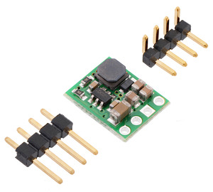
This compact (0.4″ × 0.5″) switching step-down (or buck) voltage regulator takes input voltages up to 50 V and efficiently reduces them to 3.3 V while allowing for a maximum output current of 600 mA. It has a very low dropout, so it can be used with input voltages that are within a few hundred millivolts of its output. The pins have a 0.1″ spacing, making this board compatible with standard solderless breadboards and perfboards.


Overview
The D36V6x family of buck (step-down) voltage regulators generates lower output voltages from input voltages as high as 50 V. They are switching regulators (also called switched-mode power supplies (SMPS) or DC-to-DC converters), which makes them much more efficient than linear voltage regulators, especially when the difference between the input and output voltage is large. This family includes seven versions with fixed output voltages ranging from 3.3 V to 15 V and two adjustable versions that can be set using a trimmer potentiometer:
*該系列7款具有 3.3V~15V 固定輸出電壓範圍的版本,以及 2 個可使用微調電位計設置的可調版本:
- D36V6F3:Fixed 3.3V output 固定輸出
- D36V6F5:Fixed 5V output 固定輸出
- D36V6F6:Fixed 6V output 固定輸出
- D36V6F7:Fixed 7.5V output 固定輸出
- D36V6F9:Fixed 9V output 固定輸出
- D36V6F12:Fixed 12V output 固定輸出
- D36V6F15:Fixed 15V output 固定輸出
- D36V6ALV:Adustable 2.5 – 7.5 V output 可調
- D36V6AHV:Adustable 4 – 25 V output 可調
The regulators feature short-circuit/over-current protection, and thermal shutdown helps prevent damage from overheating. The boards do not have reverse-voltage protection./穩壓器具有短路/過流保護功能,熱關斷功能有助於防止過熱造成的損壞。這些板沒有反向電壓保護。

〔Features〕:
- Input voltage: 4 V to 50 V (minimum input subject to dropout voltage considerations; see the dropout voltage section for details)
- Output voltage: 3.3 V with 4% accuracy
- Maximum output current: 600 mA (see the maximum continuous output current graph below)
- Fixed 2.1 MHz switching frequency
- High-voltage enable input can put the board into a low-power state where it draws less than 2 μA (typical)
- Low quiescent current: < 0.1 mA (see the quiescent current graph below)
- Integrated over-temperature and over-current shutoff
- Small size: 0.5″ × 0.4″ × 0.1″ (13 mm × 10 mm × 3 mm)
- Weight: 0.5 g
〔Connections〕:
This regulator has four connections: shutdown (SHDN), input voltage (VIN), ground (GND), and output voltage (VOUT).
The SHDN pin can be driven low (under 1.25 V) to turn off the output and put the board into a low-power state (< 2 μA typical). The regulator is enabled by default, and this input can be left disconnected if you do not need this feature.
The input voltage, VIN, powers the regulator. Voltages between 4 V and 50 V can be applied to VIN, but for versions of the regulator that have an output voltage higher than 4 V, the effective lower limit of VIN is VOUT plus the regulator’s dropout voltage, which varies approximately linearly with the load (see below for graphs of the dropout voltage as a function of the load). Additionally, please be wary of destructive LC spikes (see below for more information).
The four connections are labeled on the back side of the PCB and are arranged with a 0.1″ spacing along the edge of the board for compatibility with solderless breadboards, connectors, and other prototyping arrangements that use a 0.1″ grid. You can solder wires directly to the board or solder in either the 4×1 straight male header strip or the 4×1 right-angle male header strip that is included.
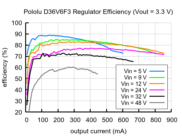
〔Typical efficiency〕:
The efficiency of a voltage regulator, defined as (Power out)/(Power in), is an important measure of its performance, especially when battery life or heat are concerns.
〔Maximum continuous output current〕:
The maximum achievable output current of these regulators varies with the input voltage but also depends on other factors, including the ambient temperature, air flow, and heat sinking. The graph below shows maximum output currents that these regulators can deliver continuously at room temperature in still air and without additional heat sinking.
〔Quiescent current〕:
The quiescent current is the current the regulator uses just to power itself, and the graph below shows this for the different regulator versions as a function of the input voltage. The module’s SHDN input can be driven low to put the board into a low-power state where it typically draws under 2 μA.
〔Typical dropout voltage〕:
The dropout voltage of a step-down regulator is the minimum amount by which the input voltage must exceed the regulator’s target output voltage in order to ensure the target output can be achieved. For example, if a 5V regulator has a 1V dropout voltage, the input must be at least 6V to ensure the output is the full 5V. Generally speaking, the dropout voltage increases as the output current increases. The graph below shows the dropout voltages for the different members of this regulator family:
〔LC voltage spikes〕:
When connecting voltage to electronic circuits, the initial rush of current can cause voltage spikes that are much higher than the input voltage. If these spikes exceed the regulator’s maximum voltage (50 V), the regulator can be destroyed. In our tests with typical power leads (~30″ test clips), input voltages above 28 V caused spikes over 50V.
If you are connecting more than 28 V or your power leads or supply has high inductance, we recommend soldering a suitably rated 33 μF or larger electrolytic capacitor close to the regulator between VIN and GND.
More information about LC spikes can be found in our application note, Understanding Destructive LC Voltage Spikes.


