洋天科技洋天科技
公司簡介訂購方式匯款確認檔案下載 聯絡我們保固說明訂單查詢討論區
電子郵件:

密碼:

忘記密碼
加入會員
  首頁 | 原廠 Arduino® | 特殊服務設計 | 轉接座及轉接板/麵包板 | 開發板/燒錄器/模擬器 | 相容 For Arudino® 週邊及配件 | 旭日 RDK開發板 系列 | OKdo系列 | Saleae 系列 | Adafruit 系列 | ArduCam 系列 | Camera 攝像頭 | ROCK 系列 | Debix系列開發板 | Raspberry Pi 樹莓派 | WalnutPi 核桃派 | Banana Pi 香蕉派 | BeagleBone 狗骨頭 | M5Stack系列 | Micro:bit (BBC)系列 | NVIDIA Jetson Nano系列 | Pololu 系列 | Pycom 系列 | Seeed 系列 | Sparkfun 系列 | WeMos 系列 | 傳感器 | Cubieboard/CubieTruck系列 | Firefly 系列 | Microduino系列 | Orange Pi 香橙派 | PCB板 | PLC 系列 | Robot 機器人 | UDOO 系列 | RedBearLab 系列 | LattePanda系列 | LittleBits 系列 | Libelium 系列 | Luxonis 相機系列 | PCduino | RobotElectronics 系列 | MageDok 顯示屏 | LCD/LCM/TFT/LVDC | Dimension Engineer 系列 | 通訊模組 | 影音器材(含轉換器) | 線材/連結器/轉換器 | 測量儀器 | 馬達/馬逹控制器/電源模組 | 其他 | 焊接/維修工具 | IC零件 | LED燈-裝飾燈 | 工作站迷你電腦 mini PC | 擴大器 | 雕刻機 | 電池 | 電腦周邊 | AI 顯卡 | 停售商品
  首頁 » 商品目錄 » Seeed 系列 » Bluetooth Bee藍芽 (LoRa)Wireless無線 » 5784
商品搜尋 進階
 |  購物車內容  |  結帳   
商品分類
  聯發科 LinkIt
  Grove Kit 套件
  Grove 傳感器系列
  Grove 擴展板/轉接板
  ReSpeaker 系列
  RF Explorer系列
  Solar Panel 太陽能板 系列
  Wio系列 Wio Link/Wio Node/Wio LTE
  Bluetooth Bee藍芽 (LoRa)Wireless無線
  Bus Blaster 系列
  Crazyflie系列
  DSO 系列
  FiPy 系列
  flick系列
  GPS GSM GPRS 系列
  LCD OLED 屏
  LED燈
  RFID/WIFI系列
  Xadow 系列
  套餐
  Al Linke
  Dangerous Prototypes
  RePhone系列
  Seeed Studio
  Tessel 系列
  Machine Vision
  Prototyping
  線材
  Robot Kit
  停售/停產
  MicroPython系列
  ODYSSEY - X86 系列
Arduino
Pololu
Seeed
Sparkfun
robot-electronics
dimensionengineering
libelium
adafruit
udoo
redbearlab
Arducam
goembed
Saleae
okdo
服務台
公司簡介
退換貨服務
訂購方式
聯絡我們
匯款確認
[<< 前一頁]  瀏覽相同分類產品 9 / 43  [下一頁 >>]
Seeeduino LoRaWAN W/GPS 擴充板 (102010129)
NT$2,030
運費NT$50
條碼5784
產品說明0

※本產品原廠代理從國外進口,有些交期較長,下訂前請詢問!

Seeeduino LoRaWAN W/GPS (102010129)


Description

Seeeduino LoRaWAN W/GPS is an Arduino development board with LoRaWan protocol and GPS function embeded, through which you can get started quickly to experience LoRa's advantage in the field of IoT.

Based on communication module RHF76-052AM, Seeeduino LoRaWAN is compatible with LoRaWAN Class A/C and supports a variety of communication frequencies. The 4 onboard standard grove connectors allow Seeeduino LoRaWan to connect with hundreds of grove sensors and actuators for Seeeduino conveniently, as a result, users are able to be more focus on the application itself without worrying about the compatibility issue between different modules.

In addition, the board has embeded an integrated lithium battery management chip that allows the board to be charged by USB interface. In low consumption mold, a full charged lithium battery can power the board for several months. By using Seeeduino LoRaWAN W/GPS, you can build an IoT application very quickly.

We also offer another version that without the embedded GPS module, please click here to find the Seeeduino LoRaWAN.


Features

  • LoRaWAN Class A/C

  • Ultra long range of communication

  • GPS communication

  • Ultra low power consumption

  • Arduino programming (based on Arduino Zero bootloader)

  • Embeded with lithim battery management chip

  • 4 Grove connectors onboard


Documents

  • For libraries and documents, please visit our Wikipage.

  • For technical discussion, please come to our Forum.

  • For projects that you would like to share with the community, please visit Recipe.


Features

  • Minimum current (3.7V lipo battery) - 2mA
  • Minimum current (3.7V lipo battery & remove PWR LED) - 80 uA

Arduino/Processor

  • ATSAMD21G18 @ 48MHz with 3.3V logic/power
  • Arduino compatible (based on Arduino Zero bootloader)
  • Embedded with lithium battery management chip and status indicator led
  • 20 GPIOs
  • 4 on-board Grove connectors
  • 18 x PWM pins
  • 6 x analog inputs
  • 1 x analog output (A0)
  • 3.3V regulator with 200mA output
  • Reset button

LoRaWAN/RHF76-052

  • 1.45uA sleep current in WOR mode (Spec of the modules, not the board)
  • High link budget of 160dB. -140dBm sensitivity and 19dBm Output power.
  • Dual band, 434/470MHz and 868/915MHz
    • 19dBm@434MHz/470MHz
    • 14dBm@868MHz/915MHz
  • Support LoRaWAN protocol, Class A/C
  • Ultra long range communication
  • Ultra low power consumption
  • Firmware upgrade
  • Small size: 23mm X 28mm with 33 pin SMT package

Warning

Unlike most Arduino & Genuino boards, the Zero runs at 3.3V. The maximum voltage that the I/O pins can tolerate is 3.3V. Applying voltages higher than 3.3V to any I/O pin could damage the board.

Specification

Item Value
Microcontroller ATSAMD21G18, 32-Bit ARM Cortex M0+
Operating Voltage 3.3V
Digital I/O Pins 20
PWM Pins All but pins 2 and 7
UART 2 (Native and Programming)
Analog Input Pins 6, 12-bit ADC channels
Analog Output Pins 1, 10-bit DAC
External Interrupts All pins except pin 4
DC Current per I/O Pin 7 mA
Flash Memory 256 KB
SRAM 32 KB
EEPROM None
Clock Speed 48 MHz
Lenght 68 mm
Width 53 mm
Weight 19.6g(without GPS), 19.9(with GPS)

Application Ideas

  • Internet of Things
  • Smart House
  • Security
  • Smart Grid
  • Intelligent Farm
  • Intelligent Park

Tip

Use Grove modules to expand your application

There are 4 Grove connects on board. If this is your first time to hear about Grove, please put had on Grove System for more details. In brief, Groves is hundreds of sensor that in standard style, which is consist of sensors, actuators, displays as well as communication.

Hardware Overview

  • 1. Micro USB - Programming and supply power to the board
  • 2. Grove connectors
  • 3. JST2.0 Lipo battery input (3.7V) and charge status led
  • 4. DFU Button - Firmware mode button
  • 5. Reset Button
  • 6. Arduino Pinout
  • 7. ICSP pins
  • 8. Firmware mode led
  • 9. Wire antenna
  • A. uFL antenna
  • B. RF module - RHF76-052AM
  • C. ARM Cortex M0 processor - ATSAMD21G18
  • D. LEDs
    • RX/TX - blink when data on UART(from/to USB)
    • L - an led connect to D13
    • PWR - power

Tip

If you want to use the 4 on-board Grove connector, please use digitalWrite(38, HIGH) to open VCC. Otherwise you can’t provide power to Grove modules.

Pin Map

Pin Name GPIO Num External Interrupt PWM Analog In Analog Out Function
0 #0 YES YES     RX(Serial)
1 #1 YES YES     TX(Serial)
2 #2 YES        
3 #3 YES YES      
4 #4   YES      
5 #5 YES YES      
6 #6 YES YES      
7 #7 YES        
8 #8 YES YES      
9 #9 YES YES      
10 #10 YES YES      
11 #11 YES YES     SPI_MOSI
12 #12 YES YES     SPI_MISO
13 #13 YES YES     SPI_SCK
SDA #20 YES YES      
SCL #21 YES YES      
A0 #A0 YES YES YES YES  
A1 #A1 YES YES YES    
A2 #A2 YES YES YES    
A3 #A3 YES YES YES    
A4 #A4 YES YES YES   Voltage of Battery
A5 #A5 YES YES YES   Charge Status

Note

All pins can act as Digital Input and Output

Getting Started - Arduino IDE

Note

This chapter is based on Win10 and Arduino IDE v1.6.0

First you need to install the latest Arduino IDE, and ADD Seeeduino LoRa to your Arduino IDE.

Install the Driver (For Windows)

When the first time to insert the board, you should get a USB COM device name Seeeduino LoRaWAN that need to install a driver. Click on the below button to download driver for the board.

To make sure the driver was installed successful, open your Device Manager to see if Seeeduino LoRaWAN exists.

Now we can upload our first demo - Blink to Seeeduino LoRaWAN.

Open your Arduino IDE and click on File > Examples > 01.Basics > Blink to open the sketch or copy the blow code:

// the setup function runs once when you press reset or power the board void setup() {
  // initialize digital pin 13 as an output.
  pinMode(13, OUTPUT);
}

// the loop function runs over and over again forever void loop() {
  digitalWrite(13, HIGH);   // turn the LED on (HIGH is the voltage level)
  delay(1000);              // wait for a second
  digitalWrite(13, LOW);    // turn the LED off by making the voltage LOW
  delay(1000);              // wait for a second
}

And Then,

  • Click on Tools > Board > Seeeduino LoRaWAN
  • Click on Tools > Port to select a right port number. (Don’t choose COM1)
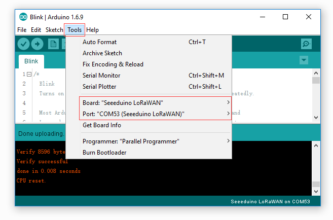
Then click on the Upload button on the left-top of Arduino IDE, seconds later the sketch was uploaded successful.
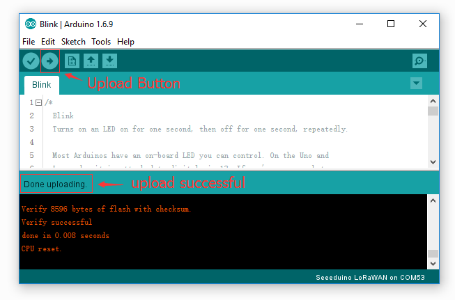
If the uploading is success, you should the some info in red and please the on-board LED, it’s blinking.

Battery

You can power the board via a 3.7V Lipo battery. There’s a JST2.0 cable included, use it if you can’t get a battery with JST2.0 connector.

Warning

Make sure the positive and negative end of your battery is connected right, otherwise the board may be damaged.

Charge status pin and positive pin of the battery had beed connect to A4 and A5, which allow you to detect the charge status and measure voltage of the battery via coding.

Copy and upload the below code to detect the battery status.

// battey of Seeeduino LoRaWAN const int pin_battery_status  = A5;
const int pin_battery_voltage = A4;

void setup() {
    SerialUSB.begin(115200);
    pinMode(pin_battery_status, INPUT);
}

void loop() {

    int a = analogRead(pin_battery_voltage);
    float v = a/1023.0*3.3*11.0;        // there's an 1M and 100k resistor divider
    SerialUSB.print(v, 2);
    SerialUSB.print('t');
    SerialUSB.println(digitalRead(pin_battery_status));

    delay(1000);
}

Note

Charge status return 0 while charging, return 1 while charge done or no battery insert.

Send and Receive Example

There is a well written library for the LoRaWAN modules, for simple applications you even don’t need to know much about the protocol about LoRa, which is complex and hard to read. And please note that you till need some acknowledge about LoRa protocol if you want an advanced application. You don’t need to download the library, it’s included in the package already. You can open it at File > Examples > LoRaWAN.

You need 2 piece of Seeeduino LoRaWAN to complete this example, one for sending and another for receiving.

Sending

Open your Arduino IDE and click on File > Examples > LoRaWAN > p2p_tx to open the sketch or you can copy the code below. This sketch will broadcast a string “Hello World!” every 3000 ms.

// Seduino LoRaWAN - TX example #include <LoRaWan.h> void setup(void) {
    SerialUSB.begin(115200);
    lora.init();
    lora.initP2PMode(433, SF12, BW125, 8, 8, 20);
}

void loop(void) {
    lora.transferPacketP2PMode("Hello World!");
    SerialUSB.println("Send string.");
    delay(3000);
}

Receiving

Open your Arduino IDe and click on File > Examples > LoRaWAN > p2p_rx to open the sketch or you can copy the code below.

// Seduino LoRaWAN - RX example
#include <LoRaWan.h>

unsigned char buffer[128] = {0, };

void setup(void)
{
    SerialUSB.begin(115200);
    lora.init();
    lora.initP2PMode(433, SF12, BW125, 8, 8, 20);
}

void loop(void)
{
    short length = 0;
    short rssi = 0;

    memset(buffer, 0, 128);
    length = lora.receivePacketP2PMode(buffer, 128,  &rssi, 1);

    if(length)
    {
        SerialUSB.print("Length is: ");
        SerialUSB.println(length);
        SerialUSB.print("RSSI is: ");
        SerialUSB.println(rssi);
        SerialUSB.print("Data is: ");
        for(unsigned char i = 0; i < length; i ++)
        {
            SerialUSB.print("0x");
            SerialUSB.print(buffer[i], HEX);
            SerialUSB.print(" ");
        }
        SerialUSB.println();
    }
}

After both of the sketch is well uploaded, open the serial monitor of the receiving board, check if you can get some data as below.
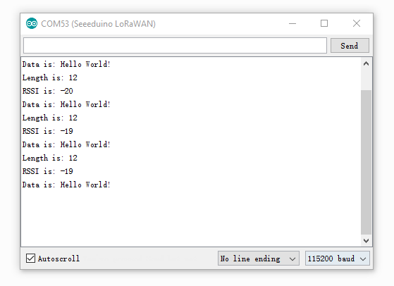
Note

There will be a gateway kit for LoRa soon, and we will add getting started about APB and OTAA mode at wiki of the kit.

Examples

We had provide many useful examples. You can open File > Examples > LoRaWan get more details. Those examples include:

  • ABP
  • OTAA
  • p2p-rx
  • p2p-tx

GPS Data

Note

This chapter works with Seeeduino LoRaWAN W/GPS only.

Copy below code you Seeeduino LoRaWAN W/GPS.

void setup()
{
    Serial.begin(9600);
    SerialUSB.begin(115200);
}

void loop()
{
    while(Serial.available())
    {
        SerialUSB.write(Serial.read());
    }
    while(SerialUSB.available())
    {
        Serial.write(SerialUSB.read());
    }
}

Open Serial Monitor then you will get data from GPS.
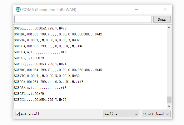
Low Power

The minimum current is 80uA(for Seeeduino LoRaWAN) under our testing. Please follow below steps.

  1. Remove PWR LED (If you don’t remove this LED, the current will > 2mA)
  2. Remove CHG LED
  3. Upload below code to your board.
#include <LoRaWan.h> #include <EnergySaving.h>

EnergySaving nrgSave;

void blink() {
    for(unsigned char i = 0; i < 5; i ++)
    {
        digitalWrite(13,HIGH);
        delay(500);
        digitalWrite(13,LOW);
        delay(500);
    }
}

void setup() {
    for(unsigned char i = 0; i < 26; i ++)      // important, set all pins to HIGH to save power
    {
        pinMode(i, OUTPUT);
        digitalWrite(i, HIGH);
    }

    lora.init();
    blink();    
    lora.setDeviceLowPower();
    blink();    
    nrgSave.begin(WAKE_EXT_INTERRUPT, 7, dummy);    // buton on D7 to wake up the board
    nrgSave.standby();
}

void loop() {
    blink();
    nrgSave.standby();
}

void dummy(void) {
    // do something
}

// END File 

Update firmware

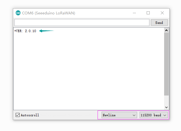
The firmware version of is 2.0.10, if you want to update firmware, few steps need to follow.

If you want to check version of you board, please upload below code to your board.

void setup()
{
    Serial1.begin(9600);
    SerialUSB.begin(115200);
}

void loop()
{
    while(Serial1.available())
    {
        SerialUSB.write(Serial1.read());
    }
    while(SerialUSB.available())
    {
        Serial1.write(SerialUSB.read());
    }
}

Open your Serial Monitor and INPUT

AT+VER 

Then you will get the version of your board.
Step1

Copy and upload below code to your board.

// Update firmware to RHF76-052AM #include <Arduino.h> void setup() {
    SerialDBG.begin(115200);
    SerialUSB.begin(115200);
}

void loop() {
    while(SerialDBG.available())
    {
        SerialUSB.write(SerialDBG.read());
    }
    while(SerialUSB.available())
    {
        SerialDBG.write(SerialUSB.read());
    }
}

Step2

Remove the board form USB and reconnect again, then press the DFU Button, after the Firmware mode led blinking you can go to the next step.

Step3

Click to download the latest firmware, which is a .bin file.

Step4

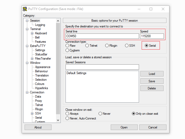
Open PuTTy and connect to the board
Tip

You can find the latest PuTTy here: http://www.extraputty.com/download.php

Step5

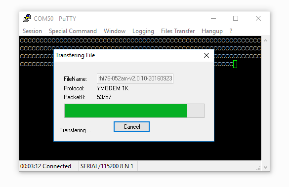
After connect your board to PuTTy successful, you will find the char ‘C’ print on the monitor continually. Click on Files Transfer > Ymodem > Send, and select the .bin file we had downloaded at Step4.

Then the updating is started.
Resources

Help us make it better

Thank you for choosing Seeed. A couple of months ago we initiated a project to improve our documentation system. What you are looking at now is the first edition of the new documentation system. Comparing to the old one, here is the progresses that we made:

  • Replaced the old documentation system with a new one that was developed from Mkdocs, a more widely used and cooler tool to develop documentation system.
  • Integrated the documentation system with our official website, now you can go to Bazaar and other section like Forum and Community more conveniently.
  • Reviewed and rewrote documents for hundreds of products for the system’s first edition, and will continue migrate documents from old wiki to the new one.

An easy-to-use instruction is as important as the product itself. We are expecting this new system will improve your experience when using Seeed’s products. However since this is the first edition, there are still many things need to improve, if you have any suggestions or findings, you are most welcome to submit the amended version as our contributor or give us suggestions in the survey below, Please don’t forget to leave your email address so that we can reply.

Happy hacking

問與答

目前沒有任何商品問答!
本商品上架日期:2013-04-30.
評價
建議購買的商品清單!可以參考看看喔
$●RM04串口轉以太網 串口轉WIFI模組 以太網轉WIFI RS232轉WIFI RJ45轉TTL 模組
購物車 更多
空的...
查詢訂單狀態
 
請輸入您的訂單編號
商品通知狀態 更多
通知Seeeduino LoRaWAN W/GPS 擴充板 (102010129)
更新時通知我
推薦給朋友
 
推薦這個商品給朋友

聯絡方式:手機:0933807110 或 0968222607
E-mail:i0104@ms13.hinet.net(主要信箱) & i03070309@yahoo.com.tw(次要) & a_te0307@hotmail.com & A9215017@mail.ntust.edu.tw & r94922042@ntu.edu.tw