※本產品原廠代理從國外進口,有些交期較長,下訂前請詢問!
新款 SparkFun Qwiic ToF Imager 模組 - VL53L3CX 晶片(SEN-18642)

The SparkFun Qwiic ToF Imager is built around VL53L5CX from ST Electronics; a state of the art, Time-of-Flight (ToF), multizone ranging sensor.

影片:https://youtu.be/TkAV8aNZ5a4

The SparkFun Qwiic ToF Imager is a state of the art, 64 pixel Time-of-Flight (ToF) 4 meter ranging sensor built around the VL53L5CX from ST. This chip integrates a SPAD array, physical infrared filters, and diffractive optical elements (DOE) to achieve the best ranging performance in various ambient lighting conditions with a range of cover glass materials. Utilizing our handy Qwiic system, no soldering is required to connect it to the rest of your system. However, we still have broken out 0.1"-spaced pins in case you prefer to use a breadboard.
Multizone distance measurements up to 4000mm are possible across all 64 zones with a wide 63° diagonal field-of-view which can be read up to 15Hz. Thanks to ST Histogram patented algorithms, the VL53L5CX is able to detect different objects within the FoV. The Histogram also provides immunity to cover glass crosstalk beyond 60cm.
Ideal for 3D room mapping, obstacle detection for robotics, gesture recognition, IoT, laser-assisted autofocus, and AR/VR enhancement, the Qwiic connector on this sensor makes integration easy.


【Features & Specs】
- Multizone ranging output with either 4x4 or 8x8 separate zones
- Autonomous Low-power mode with interrupt programmable threshold to wake up the host
- Up to 400 cm ranging
- 60 Hz frame rate capability
- Emitter:940 nm invisible light vertical cavity surface emitting laser (VCSEL) and integrated analog driver
- 63 ° diagonal square FoV using diffractive optical elements (DOE) on both transmitter and receiver
- Operating Voltage: 3.3V
- I2C Address: 0x52
- 2x Qwiic Connectors


【Note】:
The VL53L5CX is unique in that it requires its firmware to be loaded at power-on over the I2C bus. Because this firmware is ~90k bytes, we recommend a microcontroller with enough flash to store VL53L5CX's firmware as well as your program code. Sorry, Uno's are out. But didn't you want an excuse to try out something new? We recommend choosing either an Artemis Thing Plus or an ESP32 Thing Plus board as your development board.


The SparkFun Qwiic Connect System is an ecosystem of I2C sensors, actuators, shields and cables that make prototyping faster and less prone to error. All Qwiic-enabled boards use a common 1mm pitch, 4-pin JST connector. This reduces the amount of required PCB space, and polarized connections mean you can’t hook it up wrong.


《Get Started With the VL53L5CX Qwiic ToF Imager Hookup Guide》
https://learn.sparkfun.com/tutorials/qwiic-tof-imager---vl53l5cx-hookup-guide
【VL53L5CX】
注意:這兩塊電路板的感知器上都貼有真空膠帶。首次使用前請務必撕掉此膠帶!
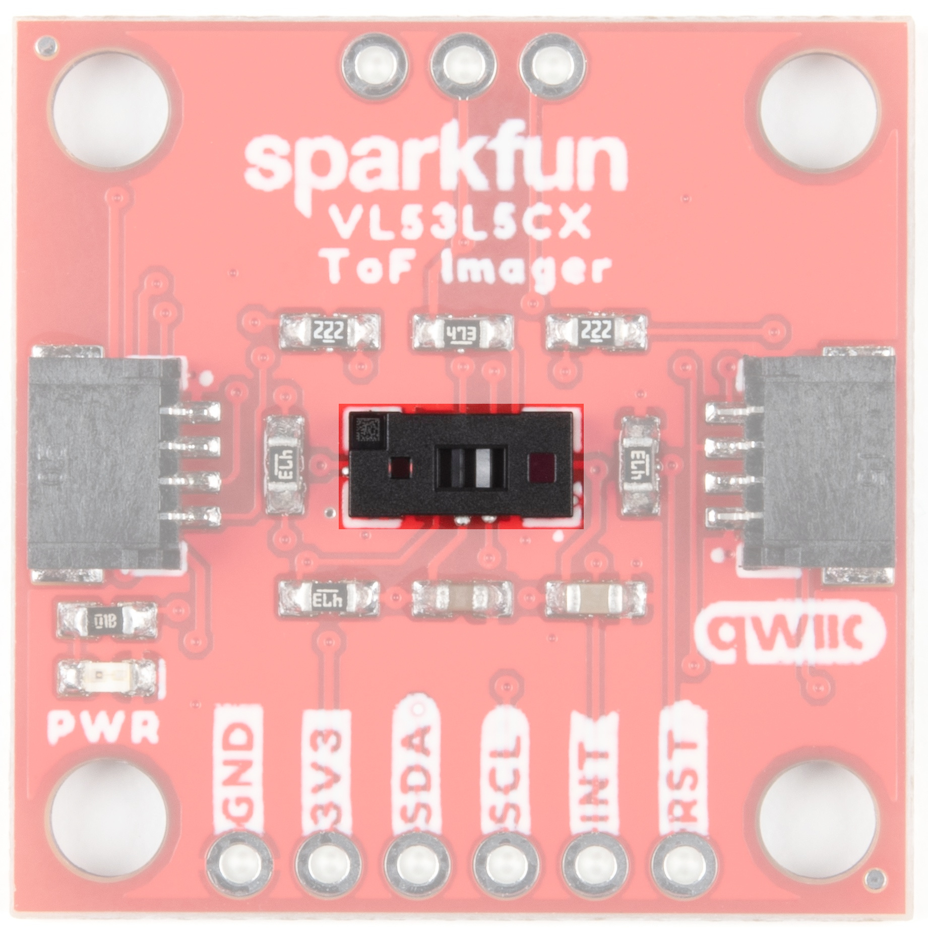 | 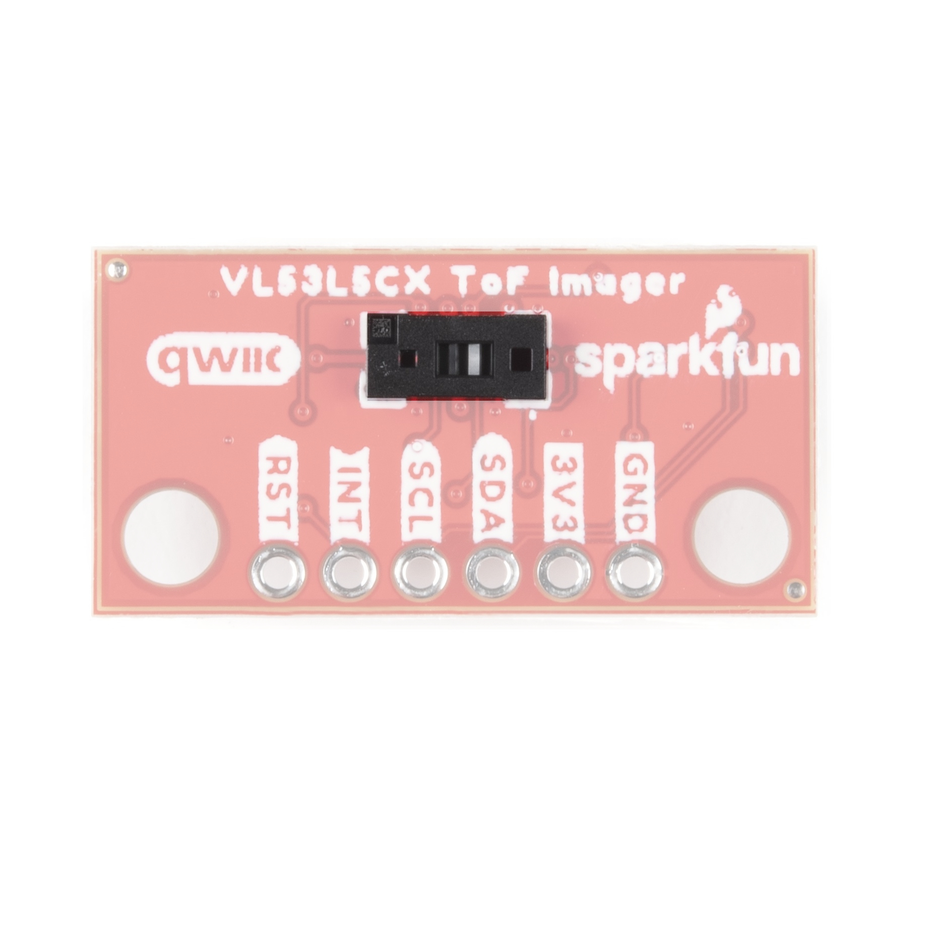 |
| Qwiic ToF 成像儀-VL53L5CX | Qwiic Mini ToF 成像儀-VL53L5CX |


【Qwiic Connectors】
Our Qwiic Ecosystem makes sensors pretty much plug and play. There are two Qwiic connectors on either side of the Qwiic Air Velocity Sensor board to provide power and I2C connectivity simultaneously.
The 7-bit unshifted I2C address (most commonly used with Arduino) is 0x29. The 8-bit I2C address of the board is 0x52 for writing and 0x53 for reading.
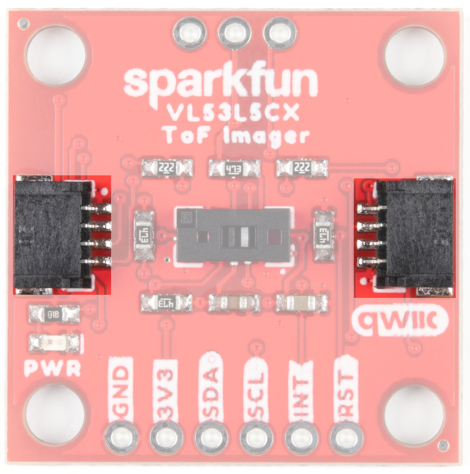 | 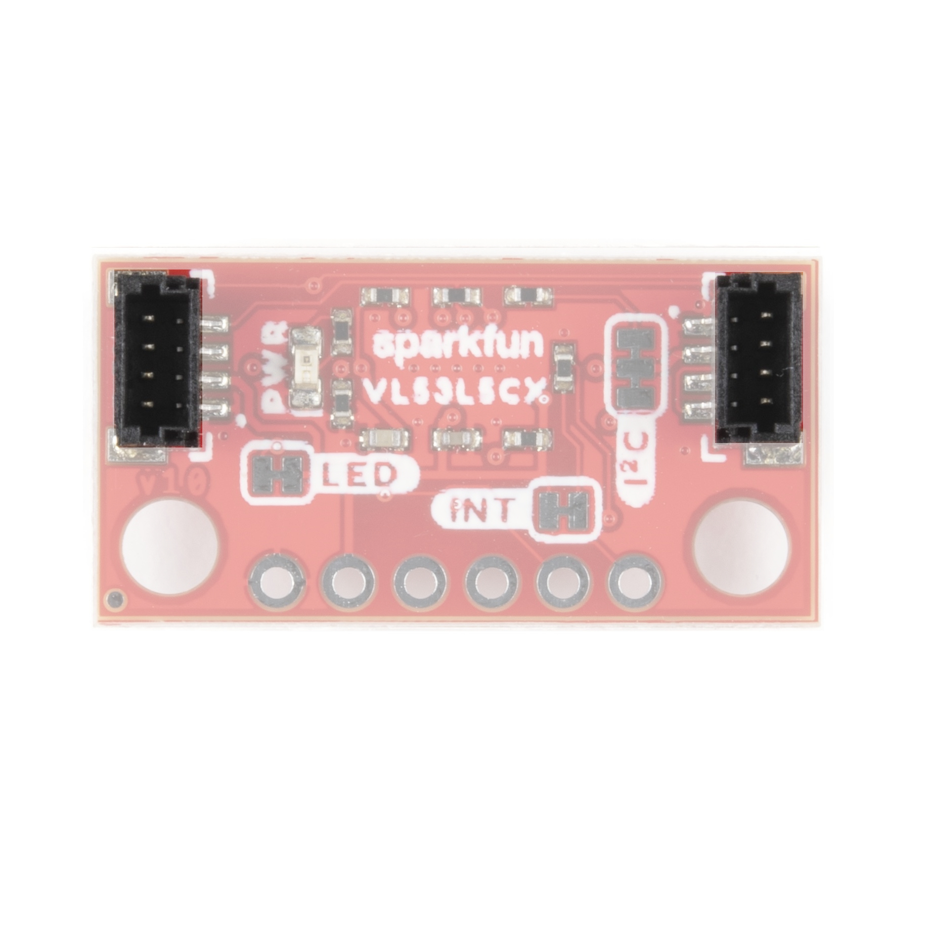 |
| Qwiic ToF Imager - VL53L5CX | Qwiic Mini ToF Imager - VL53L5CX |


【Power】
Ideally power will be supplied by the Qwiic connector, but if you wish to supply your own power, pins have been broken out along the bottom side of the board labeled 3V3 and GND. The input voltage range should be between 2.7-3.3V.
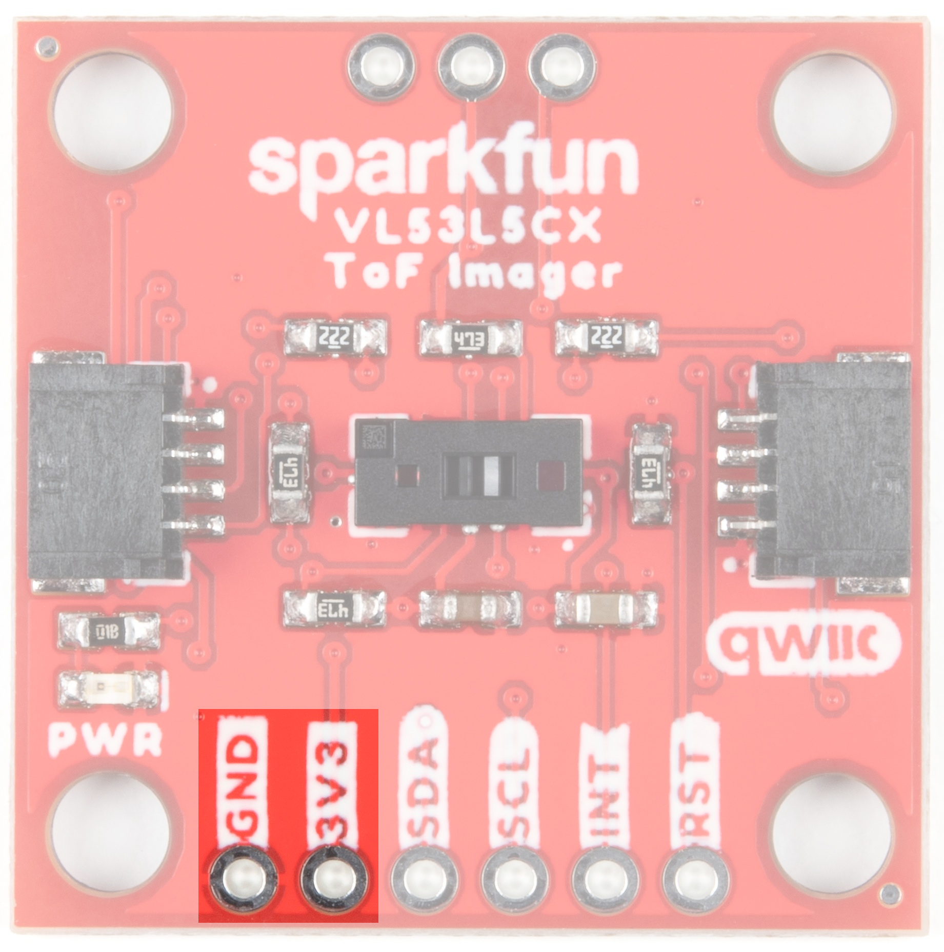 | 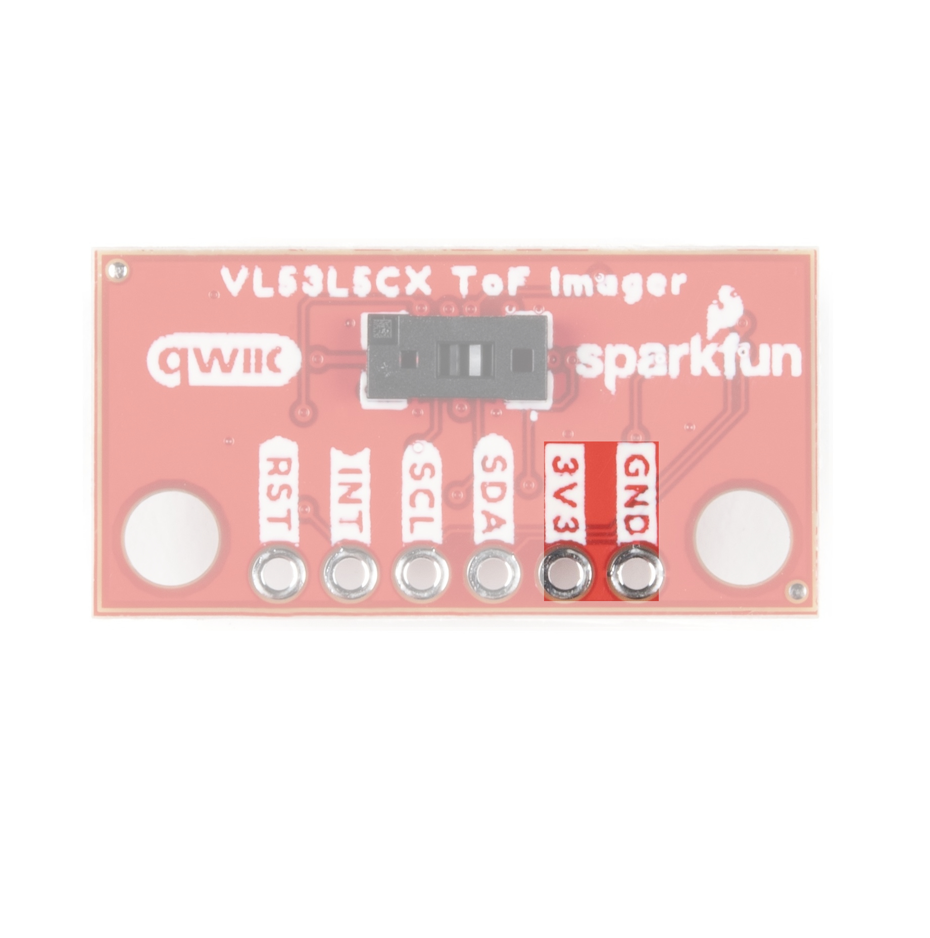 |
| Qwiic ToF Imager - VL53L5CX | Qwiic Mini ToF Imager - VL53L5CX |


【I2C】
The I2C pins break out the functionality of the Qwiic connectors. Depending on your application, you can connect to these pins via the plated through holes for SDA and SCL.
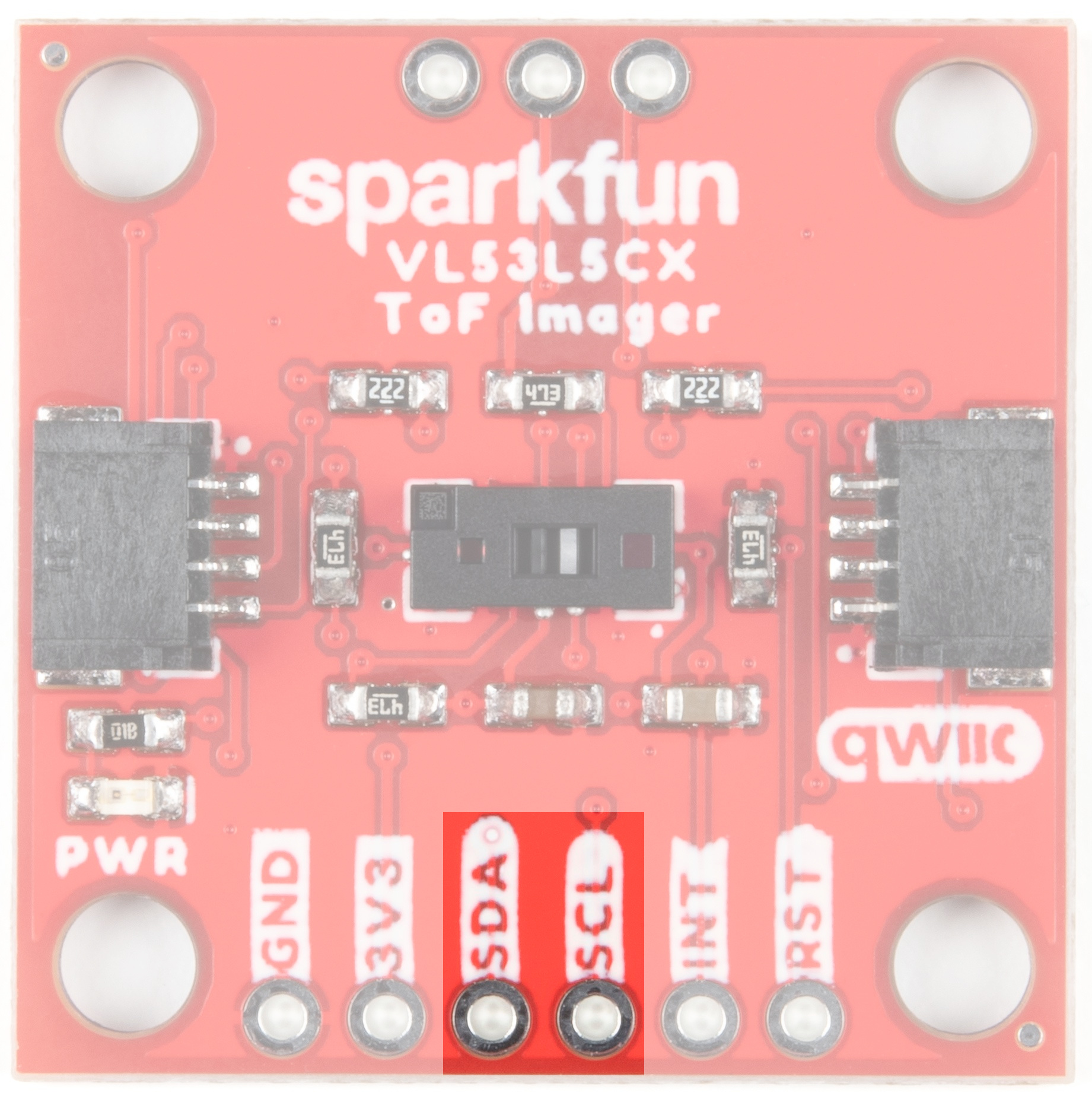 | 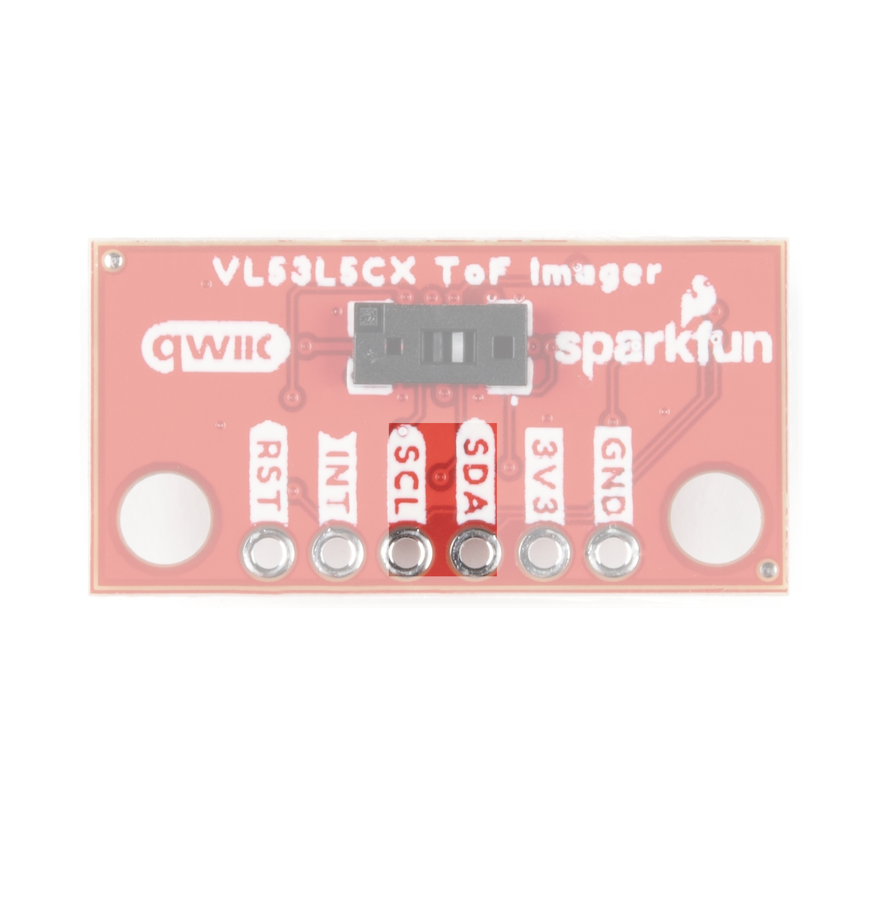 |
| Qwiic ToF Imager - VL53L5CX | Qwiic Mini ToF Imager - VL53L5CX |


【INT and RST】
The interrupt pin is the interrupt output and defaults to an open-drain output. A 47 kΩ pull-up resistor to IOVDD is included.
The reset pin is the I2C interface reset pin and is active high. It is pulled to ground with a 47 kΩ resistor.
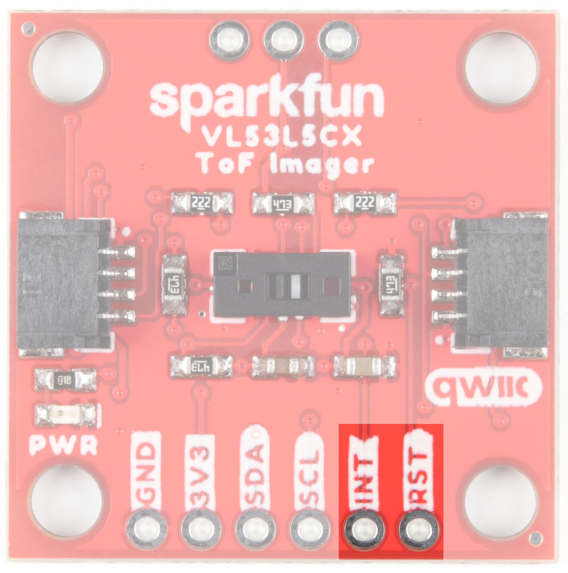 | 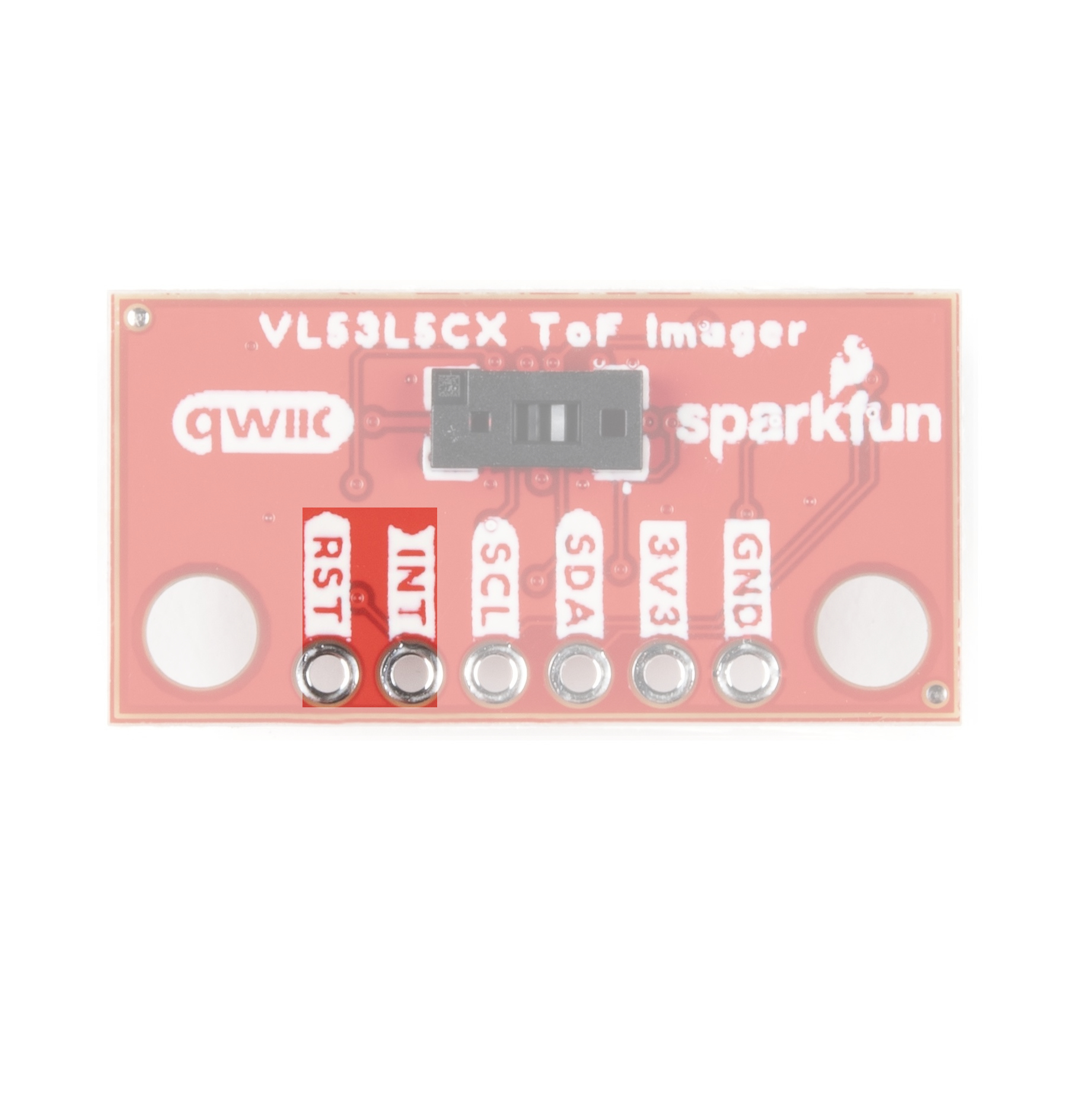 |
| Qwiic ToF Imager - VL53L5CX | Qwiic Mini ToF Imager - VL53L5CX |


【LP, VDDIO, & VDDA】
The pins in this section are specific to the 1"x1" board. LP is a low power enable pin. Drive this pin to logic 0 to disable the I2C comms to reduce power consumption. Drive this pin to logic 1 to enable I2C comms. This pin is typically only needed when you need to change the I2C address in multidevice systems. A 47 kΩ pull-up resistor to IOVDD is included so it can be left unconnected.
VDDIO/VDDA: These pins are used as an alternate power supply. By default, VDDIO and VDDA are tied together but by opening the PSU jumper they can be isolated. A user must then provide separate VDDIO and VDDA supplies. This is most applicable for users who want to use IO voltages (1.8, 2.8, or 3.3V) separate from AVDD voltages (2.8 or 3.3V) for maximum power reduction.
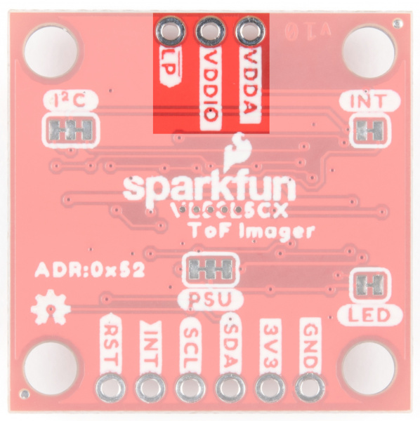


【Qwiic ToF Imager - VL53L5CX】
Click the image for a closer view


