產品說明0
RADXA Rock3 Compute module (2G+16G 帶WiFi) 核心板RK3566,可替代 RPi CM4
( 2GB/16eMMC/WIFI RM116 - D2E16W2)


相關文件

【參考資料】:
https://wiki.radxa.com/Rock3/CM3

【ROCK3 Compute Module】
Radxa ROCK3 Computing Module(Radxa CM3 series) is a series System-on-Module based on the ROCK3, containing processor, memory, eMMC Flash and Power Management Unit. These modules allow a designer to leverage the ROCK3 hardware and software stack in their own custom systems and form factors. In addition these modules have extra IO interfaces over and above what is available on the ROCK3 boards, opening up more options for the designer. ROCK3 series compute modules comes in the following form factors:
Radxa ROCK3 Computing Module(Radxa CM3系列)是基於ROCK3的系列System-on-Module,包含處理器、內存、eMMC Flash和電源管理單元。 這些模塊允許設計人員在他們自己的定制系統和外形尺寸中利用 ROCK3 硬件和軟件堆棧。 此外,這些模塊具有超出 ROCK3 板上可用的額外 IO 接口,為設計人員提供了更多選擇。 ROCK3 系列計算模塊具有以下外形尺寸
- CM3(兼容):Compatible with Raspberry Pi CM4 in pinout and form factor
- CM3 SODIMM:Compatible with Raspberry Pi CM3/CM3+, SODIMM form factor
- CM3 Industrial(工業版):Compatible with Raspberry Pi CM4 pinout in a larger size with industrial temperature range option

相關資訊

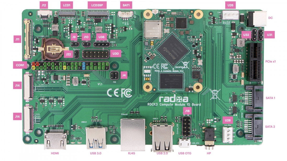
【IO底板另購】:

從 USB 端口 (Radxa CM3 IO) 將映像安裝到 eMMC:
https://wiki.radxa.com/Rock3/installusb-install-radxa-cm3-io
What you need
【Necessary】
- CM3(any variant) + CM3 IO board
- If the CM3 doesn't have eMMC, a micro SD card larger than 8GB is required for OS
- Power supply
- The main PSU input (DC) is a 2.1mm DC tip positive +12V(only) input./12V DC電源
- Monitor and HDMI Cable
- CM3 IO board is equipped with a full sized HDMI connector. HDMI capable monitor is recommended.
- HDMI EDID display data is used to determine the best display resolution. On monitors and TVs that support 1080p (or 4K) this resolution will be selected. If 1080p is not supported the next available resolution reported by EDID will be used. This selected mode will work with MOST but not all monitors/TVs.
- USB to TTL serial cable
- CM3 IO board exports a dedicated serial console for CPU, which can access the low level debug message.
- Micro USB cable
- If you want write image to CM3 eMMC from USB OTG port or use fastboot/adb commands you need a micro USB cable to connect CM3 IO board and PC.
【Power on】
Plug in the 12V DC, the CM3 should automatically boot. If the CM3 doesn't have eMMC or the eMMC is empty, plug in the micro USB to host PC, host PC should detect the CM3 in maskrom mode.
【Install image to CM3】
- Install image to SD card, refer microSD card installation
- Install image to eMMC, refer Install to eMMC from USB port (Radxa CM3 IO)
【USB 3.0】
There is one USB 3.0 A port on the IO board, supporting 5.0Gbps. The USB 3.0 function is shared with SATA2, a 1in->2out mux CH482D is used for function switching to USB 3.0 or SATA2. GPIO3_C7 is used for the route select, When GPIO3_C7 is low, signal route to USB3.0, when GPIO3_C7 is high, signal route to SATA2.
Current output limit for the USB 3.0 is 2A.
【PCIe Slot】
There is one PCIe x1 slot on the IO board, supporting 5.0Gbps. The PCIe function is shared with SATA1, a 1in->2out mux CH482D is used for function switching to PCIe or SATA1. GPIO3_C6 is used for the route select, When GPIO3_C6 is low, signal route to PCIe, when GPIO3_C7 is high, signal route to SATA1.
The PCIe on the CM3 meets PCIe 2.1 specification and support one lane and Root Complex mode only. PCIe slot power is directly from +12V DC, make sure the power supply can provide enough current for the PCIe card.
【SATA1&2】
IO board has two SATA ports compatible with Serial ATA 3.3 and AHCI Revision 1.3.1, SATA 1 is shared with USB 3.0 and SATA 2 is shared with PCIe, set the corresponding signal route to use it. Connector U28 can be used for SATA power, the +12V of U28 is directly from the +12V DC, make sure the power supply can provide enough current for the HDD.
【Micro USB】
The Micro USB port on the IO board supports host and device mode, it's used for firmware installing to eMMC from host PC or using ADB debugging. Note: When in maskrom mode, the USB OTG is forced in device mode.
20px; margin-bottom: 10px; font-size: 43px; background-color: rgb(247, 247, 247);">SATA1&2
IO board has two SATA ports compatible with Serial ATA 3.3 and AHCI Revision 1.3.1, SATA 1 is shared with USB 3.0 and SATA 2 is shared with PCIe, set the corresponding signal route to use it. Connector U28 can be used for SATA power, the +12V of U28 is directly from the +12V DC, make sure the power supply can provide enough current for the HDD.
Micro USB
The Micro USB port on the IO board supports host and device mode, it's used for firmware installing to eMMC from host PC or using ADB debugging. Note: When in maskrom mode, the USB OTG is forced in device mode.