產品說明0
※本產品原廠代理從國外進口,有些交期較長,下訂前請詢問!
ARDUINO MKR ZERO (ABX00012)
(I2S BUS & SD FOR SOUND, MUSIC & DIGITAL AUDIO DATA)
用於聲音,音樂和數字音頻數據的I2S總線和SD


MKR ZERO has an on-board SD connector with dedicated SPI interfaces (SPI1) that allows you to play with MUSIC files with no extra hardware!
Watch out music makers, we’ve got some news for you! We have released two libraries for your enjoyment:
Arduino Sound library – a simple way to play and analyze audio data using Arduino on SAM D21-based boards. I2S library – to use the I2S protocol on SAMD21-based boards. For those who don’t know, I2S (Inter-IC Sound) is an electrical serial bus interface standard for connecting digital audio devices.
-
The MKR ZERO brings you the power of a Zero in the smaller format established by the MKR form factor. The MKR ZERO board acts as a great educational tool for learning about 32-bit application development. It has an on-board SD connector with dedicated SPI interfaces (SPI1) that allows you to play with MUSIC files with no extra hardware! The board is powered by Atmel’s SAMD21 MCU, which features a 32-bit ARM Cortex® M0+ core.
MKR ZERO以MKR尺寸規格建立的較小格式為您帶來零的力量。MKR ZERO開發板是學習32位應用程序開發的一種很好的教育工具。它帶有一個帶有專用SPI接口(SPI1)的板載SD連接器,使您無需額外的硬件即可播放MUSIC文件!該板由Atmel的SAMD21 MCU提供支持,該MCU具有32位ARMCortex®M0 +內核。
Warning: Unlike most Arduino & Genuino boards, the MKRZero runs at 3.3V. The maximum voltage that the I/O pins can tolerate is 3.3V. Applying voltages higher than 3.3V to any I/O pin could damage the board.
警告:與大多數Arduino和Genuino開發板不同,MKRZero運行於3.3V。I / O引腳可以承受的最大電壓為3.3V。向任何I / O引腳施加高於3.3V的電壓可能會損壞電路板。
The board contains everything needed to support the microcontroller; simply connect it to a computer with a micro-USB cable or power it by a LiPo battery. The battery voltage can also be monitored since a connection between the battery and the analog converter of the board exists.
評估板包含支持微控制器所需的一切;只需使用micro-USB電纜將其連接到計算機或通過LiPo電池供電即可。由於電池和板的模擬轉換器之間存在連接,因此也可以監視電池電壓。
You can find
here your board warranty informations.
Getting Started
相關文件
OSH:原理圖
MKR ZERO是開源硬件!您可以使用以下文件構建自己的電路板:
.FZPZ中的邊框
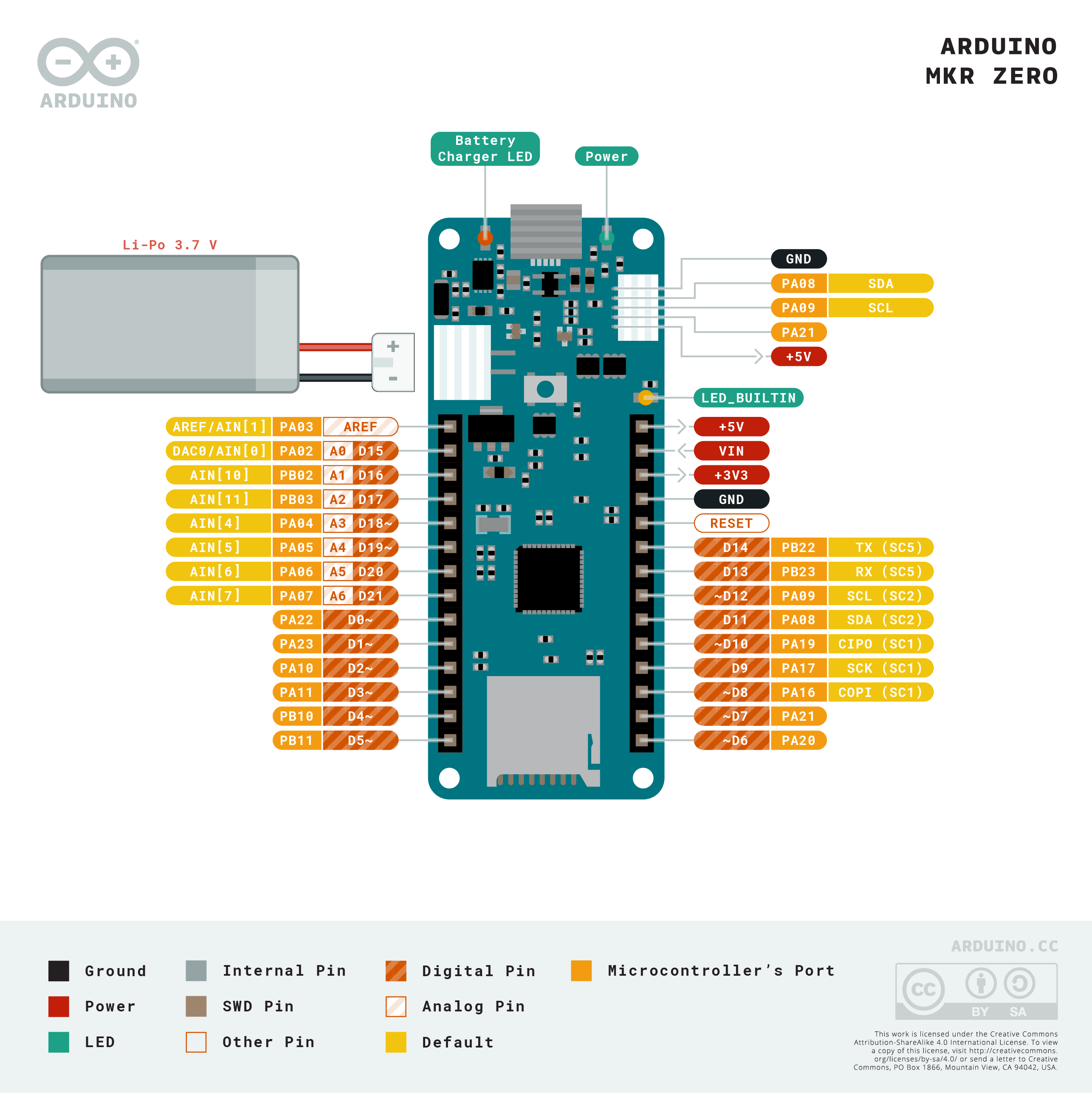
引腳圖
交互式板查看器

鋰電池,引腳,SD和板載LED
板載SD(On-board SD )
The onboard SD connector allows you to play with files without adding any extra hardware to the board. Furthermore, SD card is driven by a dedicated SPI interface (SPI1) and so any of the pins of the header is busy during SD usage. The SD library automatically recognizes the MKR ZERO and so any modification to the sketch is needed to use it apart from choosing the right SS pin (SDCARD_SS_PIN).
板載SD連接器使您可以播放文件,而無需在板上添加任何額外的硬件。此外,SD卡由專用的SPI接口(SPI1)驅動,因此在使用SD時,接頭連接器的任何引腳都處於繁忙狀態。SD庫會自動識別MKR ZERO,因此除了選擇正確的SS引腳(SDCARD_SS_PIN)外,還需要對草圖進行任何修改才能使用它。
電池容量 (Battery capacity )
Li-Po batteries are charged up to 4,2V with a current that is usually half of the nominal capacity (C/2). For Arduino MKR ZERO we use a specialized chip that has a preset charging current of 350mAh. This means that the MINIMUM capacity of the Li-Po battery should be 700 mAh. Smaller cells will be damaged by this current and may overheat, develop internal gasses and explode, setting on fire the surroundings. We strongly recommend that you select a Li-Po battery of at least 700mAh capacity. A bigger cell will take more time to charge, but won't be harmed or overheated. The chip is programmed with 4 hours of charging time, then it goes into automatic sleep mode. This will limit the amount of charge to max 1400 mAh per charging round.
鋰聚合物電池的充電電壓最高可達4.2V,電流通常為標稱容量(C / 2)的一半。對於Arduino MKR ZERO,我們使用一種專用芯片,該芯片具有350mAh的預設充電電流。這意味著鋰電池的最小容量應為700 mAh。較小的電池將被此電流損壞,並可能過熱,產生內部氣體並爆炸,著火於周圍環境。強烈建議您選擇容量至少為700mAh的鋰電池。較大的電池將需要更多時間充電,但不會受到傷害或過熱。該芯片被編程為具有4個小時的充電時間,然後進入自動睡眠模式。這會將每次充電回合的最大充電量限制為1400 mAh。
電池接頭 (Battery connector )
If you want to connect a battery to your MKRZero be sure to search one with female 2 pin JST PHR2 Type connector. Polarity : looking at the board connector pins, polarity is Left = Positive, Right = GND Connector datasheet On the MKRZero, connector is a Male 2pin JST PH Type
如果要將電池連接到MKRZero,請確保使用2針JST PHR2型陰型連接器搜索電池。極性:查看電路板連接器的引腳,極性為左=正,右= GND 連接器數據表 在MKRZero上,連接器為2針公JST PH型
額外的I2C端口 (Additional I2C Port )
The MKR Zero has an additional connector meant as an extension of the I2C bus. It's a small form factor 5-pin connector with 1.0mm pitch. The mechanical details of the connector can be found in the connector datasheet. The I2C port in addition to the SDA and SCL signals includes the GND and +5V power rails and a digital pin that might be useful when designing an expansion. The pinout is shown in the following image:
MKR Zero帶有一個附加的連接器,作為I2C總線的擴展。這是一種尺寸為1.0mm的小型5針連接器。連接器的機械細節可在 連接器數據表中 找到 。除SDA和SCL信號外,I2C端口還包括GND和+ 5V電源軌以及一個數字引腳,這在設計擴展時可能會有用。下圖顯示了引腳排列:

我們建議為該額外的I2C端口使用的連接器是SHR-05V-SB,如圖所示。
Vin
This pin can be used to power the board with a regulated 5V source. If the power is fed through this pin, the USB power source is disconnected. This is the only way you can supply 5v (range is 5V to maximum 6V) to the board not using USB. This pin is an INPUT.
5V
This pin outputs 5V from the board when powered from the USB connector or from the VIN pin of the board. It is unregulated and the voltage is taken directly from the inputs. As an OUTPUT, it should not be used as an input pin to power the board.
VCC
This pin outputs 3.3V through the on-board voltage regulator. This voltage is the same regardless the power source used (USB, Vin and Battery).
LED ON
This LED is connected to the 5V input from either USB or VIN. It is not connected to the battery power. This means that it lits up when power is from USB or VIN, but stays off when the board is running on battery power. This maximizes the usage of the energy stored in the battery. It is therefore normal to have the board properly running on battery power without the LED ON being lit.
CHARGE LED
The CHARGE LED on the board is driven by the charger chip that monitors the current drawn by the Li-Po battery while charging. Usually, it will lit up when the board gets 5V from VIN or USB and the chip starts charging the Li-Po battery connected to the JST connector. There are several occasions where this LED will start to blink at a frequency of about 2Hz. This flashing is caused by the following conditions maintained for a long time (from 20 to 70 minutes): - No battery is connected to JST connector. - Overdischarged/damaged battery is connected. It can't be recharged. - A fully charged battery is put through another unnecessary charging cycle. This is done disconnecting and reconnecting either VIN or the battery itself while VIN is connected.
Onboard LED
On MKR ZERO the onboard LED is connected to a dedicated pin (32) and not to 13 as on other boards. It is so suggested to use the LED_BUILTIN define .
(*) Note: DO NOT CONNECT to the male JST connector present on the board anything else than a Li-Po battery whose characteristics are compliant with those indicated above. Please DO NOT POWER VIN with more than 5V.
相關資訊
Q: I plugged the board to my PC / MAC but I cannot see the serial port listed on the IDE, I cannot upload sketch to the board!
A: The first thing to try is manually put the CPU into bootloader mode, this is accomplished by pressing quickly twice the reset button (you need a pencil to actually push the button). Another try is to change the USB cable: some micro-USB cables are "power only", you'll see the board powered but no data connection to the PC.
Q: I plugged the board, I can see the serial port but I cannot upload sketch
A: If still on, remove the conductive foam that protects the pins.
Q: What's the pin number of the onboard LED? Pin 13 seems to not work...
A: The LED is connected to a dedicated pin. Use the LED_BUILTIN constant instead of declaring the pin number.
Q: What does the CHRG LED blinking indicate?
A: Indicates that the board is charging the LiPo battery connected to the white JST connector. Please note that the charger use a constant current of 350mA, this means that you must use a LiPo battery with a minimum capacity of 700mAh otherwise you risk unpleasant side-effects like flames and/or explosions.
Q: After some time the Charge LED starts blinking even if no battery is attached to the JST connector
A: The CHARGE LED on the board is driven by the charger chip. This LED starts to blink at a frequency of about 2Hz (slow blink) if a defective or no battery is connected to the JST connector.
Q: I see that A0 is marked as DAC0. There is a DAC on that pin? is usable?
A: Yes, there is a DAC and it's usable, you can control the pin with analogWrite(..).
Q: Which is the VIN range voltage value?
A: VIN Nominal voltage value is 5V, range is from 5V to 6V (6V is the Maximum)
Q: Which is the polarity of the battery?
A: Looking at the connector pins: Left = Positive, Right = GND
Q: How can I use the on-board SD?
A: The on-board is connected to a dedicated SPI interface. The SD library deals with it, so you use the library as usual. Use SD.begin() without specify any pin number, the number will fallback to the right one.
Q: What Vin, 5V and VCC means?
A: Vin. This pin can be used to power the board with a regulated 5V source. If the power is fed through this pin, the USB power source is disconnected. This is the only way you can supply 5v (range is 5V to maximum 6V) to the board not using USB. This pin is an INPUT. 5V. This pin outputs 5V from the board when powered from the USB connector or from the VIN pin of the board. It is unregulated and the voltage is taken directly from the inputs. When powered from the battery it supplies around 3.7 V. As an OUTPUT, it should not be used as an input pin to power the board. VCC. This pin outputs 3.3V through the onboard voltage regulator. This voltage is the same regardless the power source used (USB, Vin and Battery).


